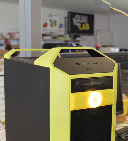
In this tutorial, you will be introduced a way to customize your CoolerMaster case with a RVB LED circular ribbon controllable through a Chrome APP (application can be run from Chrome directly) which will allow you to customize LEDs animation : colour, speed etc…
This kit requires no modification of your case which remain the same. The installation can be done in less than 2 minutes with a production cost inferior to 30 euros.
If you do not want to do the kit yourself, you will soon be able to get it on the online shop of the Maker Made of CoolerMaster,
You can also contact us now to order some of the models we have in stock.
For the makers, you will need :
1 x microcontroller Arduino Uno (12 € at DIRobots.com)
1 x Sensor Shield V5 for simplified connection (not necessary but recommanded if you plan on adding other LED ribbons)
1 x ring 12 leds at semageek 9 € or a LED ribbon (from 2 to 36 leds…)
3 x 60 cm wires with Dupont female sheets (to recycle from an old computer, these are the cables connecting the front LEDs to the motherboard)
3 parts to print in 3D (abs or white pla to paint) : download the STL
The software to upload into your arduino : download code ring-mastercase5.zip
and the software to customize the colour and the animation of the LEDs :
A 4 parts Assembly :
1 / Customization with 3D printing
We decided to use one of the front slots : DVD player or something else to create a 3D component which snaps and fits with the 12 LEDs.
Parts to print :
Made in ABS or PLA with a sharpness of 0.2 and a filling of 20%. If you do not have a 3D printer, localize the closest FAB LAB, they will be pleased to help : FAB LAB map.
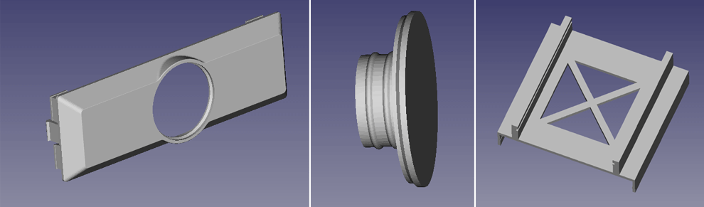
Download the STL files of the 3D parts to print
– capot_optimisation_8D.stl
– support_ring_optimisation2.stl
– support-arduino-coolermaster.stl
2/ Control Electronics with Arduino
Load the Arduino into the slide of the printed medium, the whole snaps on one of the two hoods allocated to the hard drive.
The Arduino is powered and steered via a USB wire plugged to the computer.
You can control up to 12 LEDs ribbons… or even servo motors… If the electric power were to be insufficient you have the possibility to switch to the shield (for usb2 from 500 mA).
Weld the 3 wires to the ring :
+5v,
– mass
– wire for control on Data In.
And at the opposite end, a Dupont 3 plug connector, with the following order :
[Mass ] [+5V] [Order]
The control wire will have to be positionned on a pin marked S (Signal) on the shield.
Assemble the shield on the Arduino as shown in the pictures below.
3 / Software to upload into Arduino
The microcontroller Arduino has be adjusted according to our needs. The Arduino IDE will have to be installed, and the Adafruit Neopixel Il vous faudra installer l’IDE arduino, et la bibliothèque Adafruit_NeoPixel allowing the management of the LED ring and to load the code : download code ring-mastercase5.zip.
We use the default pin n°10 to manage the ring, but nothing will prevent you to reallocate your LEDs to another one by modifying the variables atop the program.
If your LED ring is composed of at least 12 LEDs, change the NUMPIXELS variable.
#define PIN 10
#define PINSTRIP 9
// How many NeoPixels are attached to the Arduino?
#define NUMPIXELS 16
#define NUMPIXELSSTRIP 16
Once the program is downloaded into the Arduino, open the serie editor and configure it into 38 400 baud and CR/NL then type help to get the possible commands (for the geeks :-).
For instance, to start an animation with red colored LEDS and the effect n°1 :
RVB#ff0000
EFFE1
If you wish to have this animation at the start of your computer, click on save to memorise the adjustment in EEPROM.
If the use of the command line seems to somehow be boring, keep on reading 🙂 and discover the user-friendly software we have created to manage the light effects software we have developed.
4 / Installing the « LED modding controller for Arduino » into the google Chrome browser.
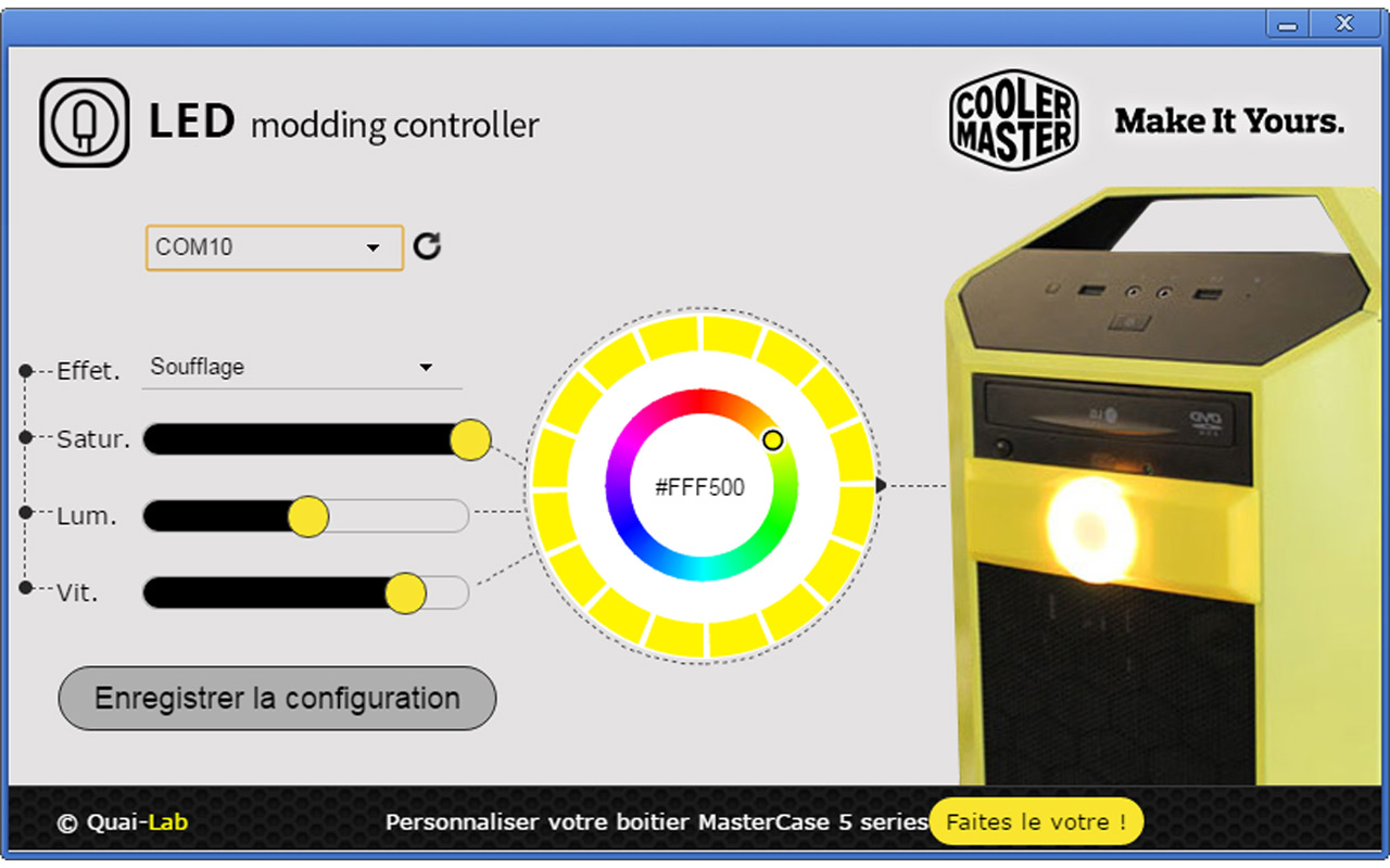
Final step, rather than setting-up your LEDs using command lines via the serie monitor, install the application with the Chrome Store : LED Modding controller using the following link : Download the application with Chrome Web Store
Or by searching for the application in the Chrome Store under the name « LED Modding Controller »
At the initiation of the application, choose the usb port on which your arduino is positionned, the interface will automatically reconfigure itself to display the number of LEDS declared by the Arduino script.
Using your mouse, you can now set up colours, choose to switch on or to switch off the LEDs, put a speed effect etc…
Once satisfied with your animation, click on [save the configuration]. This configuration will be written into the Arduino memory and will run it automatically.